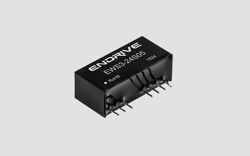
dcdc module power supply characteristics | 
|
◆Ultra-wide input voltage range: 4:1 (9-36V, 18-72V, etc.)
◆Working temperature range: -40℃~+85℃
◆Short circuit protection (self-recovery)
◆Small volume, SIP package
◆Isolation voltage 1500VDC
◆Flame retardant package, meets the requirements of UL94-V0
◆Complied with RoHS command |
dcdc module power supply application range |
Power systems such as wireless network, telecommunications/data communications, power systems, industrial control systems, measurement instruments and instrumentation, and intelligent fields. It is suitable for designs such as large fluctuations in the input range, small power isolation, and small layout space, and to achieve modular product functions to improve product reliability. |
dcdc module power supply model |
model | Input voltage range | Output voltage/output current Vo/Io | Efficiency (TYP) |
EWS3-24S05 | 9 – 36 VDC | 5V / 600mA | 76% |
EWS3-24S06 | 9 – 36 VDC | 6V / 600mA | 78% |
EWS3-24S12 | 9 – 36 VDC | 12V / 250mA | 79% |
EWS3-24S15 | 9 – 36 VDC | 15V / 200mA | 81% |
EWS3-48S05 | 18 – 72 VDC | 5V / 600mA | 77% |
EWS3-48S12 | 18 – 72 VDC | 12V / 250mA | 78% |
EWS3-48S15 | 18– 72 VDC | 15V / 200mA | 80% |
EWS3-24D05 | 9 – 36 VDC | ±5V / ±300mA | 78% |
EWS3-24D12 | 9 – 36 VDC | ±12V / ±125mA | 79% |
★EWS3-24D15 | 9 – 36 VDC | ±15V / ±100mA | 81% |
EWS3-48D05 | 18 – 72 VDC | ±5V / ±300mA | 76% |
EWS3-48D12 | 18 – 72 VDC | ±12V / ±125mA | 79% |
★EWS3-48D15 | 18– 72 VDC | ±15V / ±100mA | 80% |
* If you have any other specifications and models, you can contact our company directly. |
dcdc module power supply characteristics |
project | Test conditions | Min | Typ | Max | unit |
Output voltage accuracy | Input voltage range, 100% load (main circuit) |
| ±1 | ±2 | % |
| Input voltage range, 100% load (auxiliary circuit) |
| ±2 | ±5 |
|
Load adjustment rate | Load from 10% to 100% (main circuit) |
| ±0.5 | ±0.75 |
|
| From 10% to 100% load (auxiliary circuit) |
| ±0.5 | ±1.0 |
|
Voltage adjustment rate | Input voltage range |
| ±0.2 | ±0.5 |
|
Output short circuit protection | Sustainable, self-recovery |
Ripple & Noise | 20MHz bandwidth, nominal voltage input 100% load |
| 35 | 75 | mVp-p |
Switching frequency | Input voltage range 100% load | 120-300(PFM) | KHz |
Temperature drift coefficient | Nominal voltage input 100% load, -40℃~ +85℃ |
|
| ±0.03 | %/℃ |
Storage humidity |
|
|
| 95 | % |
Operating temperature | Safe workspace for product compliance | -40 |
| 85 | ℃ |
Storage temperature |
| -50 |
| 125 |
|
The shell heats up when the product works | Nominal voltage input 100% load |
| 20 |
|
|
Pin resistance to soldering temperature | The solder joint is 1.5mm from the edge of the shell, 10 seconds |
|
| 300 |
|
Insulation strength | Test time for 1 minute, leakage current is less than 0.5mA | 1500 |
|
| VDC |
Insulation resistor | Insulation voltage 500VDC | 1000 |
|
| MΩ |
Cooling method | Natural air-cool |
Housing material | Flame retardant and heat-resistant plastic |
Average failure-free time | MIL-HDBK-217F@25℃ | 100 |
|
| Ten thousand hours |
weight |
|
| 5 |
| gram |
Note: 1. Except for special instructions, the above data are measured under TA=25℃ and humidity <75%;
2. Other specifications can also be provided. Please contact our company for details. |
Typical Applications |

Notes on using:
Requirements for input power supply
A low-impedance voltage source must be connected to the input end of the product. If the voltage source impedance is too high or the connection line between the voltage source and the input end of the product is too long, the product will be instable. Connecting a low ESR capacitor to the input end of the product (as close as possible to the input pin of the product) can effectively solve the occurrence of this problem. For example, a 24V input product can be connected to a 22μF capacitor. ② Reduce output ripple
If further reduction of output ripple is required, a suitable filter capacitor can be connected in parallel at the output end or connected to an "LC" filter network. It should be noted that the external capacitor at the output end cannot be too large, otherwise it may cause startup problems. Please refer to the product's *** output capacitive load requirements for details. The bandwidth of the "LC" filter network should be far from the product's operating frequency range. Generally speaking, connecting a low ESR filter capacitor to the output end can meet the requirements, usually Co=100uF. ③ Input current
When the input power supply voltage is unstable, please make sure that its output voltage fluctuation range meets the input requirements of the product; the output current of the input power supply must be sufficient to cope with the instantaneous start current Ip of the product, generally: Ip = 2-4*Iin-max. ④ This product cannot be used in parallel and does not support hot plugging. |
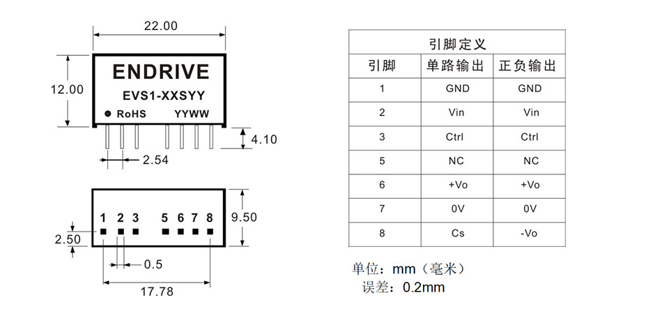
Appearance size and pin mode |

|