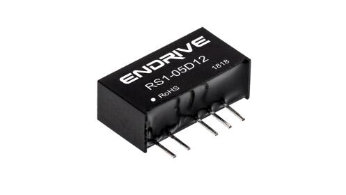
Product Features | 
|
◆ Input voltage range: 10 % ◆ Small size, SIP package ◆ Isolation 1 5 00VDC / 3000VDC (H) ◆ Working temperature range: -40 ℃~+85 ℃ ◆ Firetretardant packaging, meets the requirements of UL94-V0 ◆ Complied with RoHS Directive |
Application scope |
Power systems such as wireless network, telecommunications/data communications, power systems, industrial control systems, measurement instruments and instrumentation, and intelligent fields. It is suitable for designs such as large fluctuations in the input range, small power isolation, and small layout space, and to achieve modular product functions to improve product reliability. |
Product model |
model | Input voltage range | Output voltage/output current Vo/Io | Efficiency (TYP) |
RS1 -05S05 ( H ) | 4.5 – 5.5 VDC | 5V / 200mA | 72% |
RS1 -05S12 ( H ) | 4.5 – 5.5 VDC | 12V / 83mA | 78% |
RS1 -05S15 ( H ) | 4.5 – 5.5 VDC | 15 V / 67mA | 79% |
RS1 -12S05 ( H ) | 10.8 – 13.2 VDC | 5V / 200mA | 76% |
RS1 -12S12 ( H ) | 10.8 – 13.2 VDC | 12V / 83mA | 80% |
RS1 -12S15 ( H ) | 10.8 – 13.2 VDC | 15 V / 67mA | 80% |
RS1 -24S05 ( H ) | 21.6 – 26.4 VDC | 5V / 200mA | 74% |
RS1 -24S12 ( H ) | 21.6 – 26.4 VDC | 12V / 83mA | 77% |
RS1 -24S15 ( H ) | 21.6 – 26.4 VDC | 15 V / 67mA | 78% |
RS1 -05D05 ( H ) | 4.5 – 5.5 VDC | ±5V / ±100mA | 74% |
RS1 -05D12 ( H ) | 4.5 – 5.5 VDC | ± 12 V / ± 42 mA | 79% |
RS1 -05D15 ( H ) | 4.5 – 5.5 VDC | ± 1 5V / ± 33 mA | 80% |
RS1 -12D05 ( H ) | 10.8 – 13.2 VDC | ±5V / ±100mA | 74% |
RS1 -12D12 ( H ) | 10.8 – 13.2 VDC | ± 12 V / ± 42 mA | 80% |
RS1 -12D15 ( H ) | 10.8 – 13.2 VDC | ± 1 5V / ± 33 mA | 80% |
RS1 -24D05 ( H ) | 21.6 – 26.4 VDC | ±5V / ±100mA | 77% |
RS1 -24D12 ( H ) | 21.6 – 26.4 VDC | ± 12 V / ± 42 mA | 79% |
RS1 -24D15 ( H ) | 21.6 – 26.4 VDC | ± 1 5V / ± 33 mA | 80% |
Note: The model with H is isolated 3000VDC product Model without H is isolated 1500VDC |
Product Features |
project | Test conditions | Min | Typ | Max | unit |
Output voltage accuracy | Input voltage range, 100% load | -7.5 |
| +10 | % |
Load adjustment rate | From 10% to 100% load | -7.5 |
| +10 |
Voltage adjustment rate | Input voltage range | -1.2 |
| +1.2 |
Output short circuit protection | 1s |
Ripple & Noise | 20MHz bandwidth, nominal voltage input 100% load |
| 100 | 150 | mVp-p |
Switching frequency | Input voltage range 100% load | 100 | KHz |
Temperature drift coefficient | Nominal voltage input 100% load, -40 ℃ ~ +85 ℃ |
|
| ±0.03 | %/℃ |
Storage humidity |
|
|
| 95 | %RH |
Operating temperature | Safe workspace for product compliance | -40 |
| 85 | ℃ |
Storage temperature |
| -55 |
| 125 |
The casing heats up during operation | Nominal voltage input 100% load |
| 15 |
|
Pin resistance to soldering temperature | The solder joint is 1.5mm from the edge of the shell, 10 seconds |
|
| 300 |
Insulation strength | Test time for 1 minute, leakage current is less than 0.5mA | 1500 / 3000 (H) | VDC |
Insulation resistor | Insulation voltage 500VDC | 1000 |
|
| MΩ |
Cooling method | Natural air-cool |
Housing material | Flame retardant and heat-resistant plastic |
Average failure-free time | MIL-HDBK-217F@25 ℃ | 100 |
|
| Ten thousand hours |
weight |
|
| 2.1 |
| gram |
Note: 1. Except for special instructions, the data listed above are measured under the conditions of TA=25℃ and humidity <75%. 2. Other specifications can also be provided for input and output. Please contact our company for details. |
Typical Applications |

Notes on using: The selection of inductance values ​​and the frequency of the "LC" filtering network should be staggered from the DC/DC frequency to avoid mutual interference. And choose a suitable filter capacitor. If the capacitor is too large, it may cause startup problems. For each output, the recommended capacitive load value is shown in (Table 1). Recommended capacitive load values ​​(Table 1) Output voltage (VDC) external capacitor (uF) 3.3/54.792.2122.2151241For applications where the actual output power is less than 0.5W, it is recommended not to connect external capacitors
|
②Overload protection Under normal operating conditions, the product output circuit has no protection function for overload conditions. The simplest way is to connect a self-recovery fuse in series at the input, or add a circuit breaker to the circuit.
③ 输入过压保护电路 对于输入过压保护的***简单的装置是在其输入端串接一个带过热保护的线性稳压器。
④ 此产品不能并联使用,不支持热插拔 |
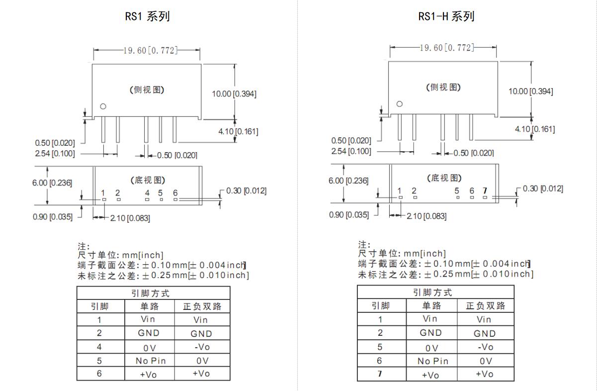
外观尺寸和引脚方式 |
 |