Product Features
Industry-standard DIP packaging
Operating temperature range: -40 ℃ to +85 ℃
*** Can connect to 64 nodes
Single input power supply
Electromagnetic radiation EMI is very low
Application fields: industrial communications , coal mining industry, power monitoring , building automation
Product Description
TD301D485H / TD501D485H, the main function will be to convert the logic level to the differential level of the RS-485 protocol to achieve signal isolation; it is an RS-485 protocol transceiver module that uses IC integration technology to realize power isolation, signal isolation, RS-485 communication and bus protection. The product comes with a fixed voltage isolation power supply, which can achieve 2500VDC electrical isolation. The product can be easily embedded in user equipment, making the device easy to realize the connection function of the RS-485 protocol network.
Selection table
Product model | Power supply voltage range (VDC) | Quiescent current (mA,Typ) | Operating current (mA) | Transmission baud rate (kbps) | Number of nodes (pcs) |
TD 301 D485H | 3.3 (3.15~3.45) | 33 | 120 | 115.2 | 64 |
TD 501 D485H | 5 (4.75~5.25) | 28 | 100 | 115.2 | 64 |
Extreme parameters
project | condition | Small value | Nominal value | Large value | unit |
Input voltage range | TD 301 D485H | -0.7 | 3.3 | 5 | Vdc |
TD 501 D485H | -0.7 | 5 | 7 |
Pin resistance to soldering temperature | Manual welding@3~5 seconds | -- | 370 | -- | ℃ |
Wave soldering@5~10 seconds | -- | 265 | -- |
Hot plug | -- | Not supported |
Note: This series of modules does not input anti-reverse connection function, and it is strictly forbidden to input positive and negative connections, otherwise the module will be irreversible and damaged.
Input Features
project | symbol | condition | Small value | Nominal value | Large value | unit |
Input voltage | V CC | TD 301 D485H | 3.15 | 3.3 | 3.45 | V DC |
TD 501 D485H | 4.75 | 5 | 5.25 |
TXD logic level | High level | V IH |
| 0.7V CC | -- | V CC +0.5 |
Low level | V IL |
| 0 | -- | 0.3V CC |
RXD logic level | High level | V OH | I RXD =4mA | V CC -0.4 | V CC -0.2 | -- |
Low level | V OL | I RXD =4mA | -- | 0.2 | 0.4 |
CON control level | High level | V CON_H | TD 301 D485H | 2.3 | -- | V CC +0.5 |
TD 501 D485H | 3.8 | -- | V CC +0.5 |
Low level | V CON_L |
| 0 | -- | 0.3V CC |
TXD drive current | I TXD |
| 2 |
|
| mA |
CON drive current | I CON |
| 5 |
|
|
RXD output current | I RXD |
|
|
| 10 |
TXD pull-up resistor | R TXD |
|
| 10 |
| kΩ |
Serial interface | TD 301 D485H | 3.3V standard UART interface |
TD 501 D485H | 5V standard UART interface |
Output Characteristics
project | symbol | condition | Small value | Nominal value | Large value | unit |
Isolated output power supply voltage | V O | Nominal input voltage | 4.95 | 5.15 | 5.35 | VDC |
Isolated output power supply current | I O | -- | -- | 100 | mA |
Differential output voltage (AB) | V OD | Nominal input voltage, differential load is 54 Ω | 1.5 | -- | VO | VDC |
Differential output current (AB) | I OD | 28 | -- | -- | mA |
Bus interface protection |
| ESD electrostatic protection |
Transmission characteristics
project | symbol | condition | Small value | Nominal value | Large value | unit |
Built-in pull-down resistor |
|
| -- | twenty two | -- | kΩ |
Transceiver input impedance |
| -7V≤VCM≤+12V | 96 | -- | -- |
Data sending delay |
|
| -- | 400 | -- | ns |
Data reception delay |
|
| -- | 150 | -- |
Send and receive status delay | T RTT , T TTR | -- | -- | 25 | -- | μs |
True table characteristics
project | enter | Output |
Send function | CON | TXD | A | B |
0 | 1 | 1 | 0 |
0 | 0 | 0 | 1 |
Receive function | CON | V A -V B | RXD |
1 | ≥-10mV | 1 |
1 | ≤-200mV | 0 |
1 | -200mV<V A -V B<-10mV | Uncertain state |
General Features
project | condition | Small value | Nominal value | Large value | unit |
Electrical isolation |
| Isolated at both ends (input and output are isolated from each other) |
Isolation voltage | Test time for 1 minute, leakage current <5mA, humidity <95% | -- | 2.5K | -- | VDC |
Operating temperature range | The output is full load | -40 | -- | +85 | ℃ |
Storage temperature | -- | -55 | -- | +105 | ℃ |
Storage humidity | No condensation | -- | -- | 95 | % |
Case temperature rise during operation |
| -- | 20 | -- | ℃ |
Usage environment | The surrounding environment has dust, strong vibration, shock and gases that corrode the product components may cause damage to the product. |
Physical characteristics
project | condition |
Housing material | Black flame retardant heat-resistant plastic (UL94-V0) |
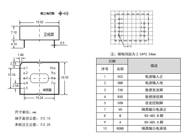
Package size | 19.50*16.50*7.10mm |
weight | 4.0g (nominal) |
Cooling method | Natural air-cool |
EMC Features
Classification | project | parameter | grade |
EMS | Electrostatic discharge immunity | IEC/EN 61000-4-2 Contact ±4KV/Air ±8KV (bare metal) | Perf.Criteria B |
IEC/EN 61000-4-2 Contact ±8KV/Air ±15KV (recommended circuits are shown in Figure 2/Figure 3) | Perf.Criteria B |
Pulse group immunity | IEC/EN 61000-4-4 ±2KV | Perf.Criteria B |
Lightning surge immunity | IEC/EN 61000-4-5 Common mode ±2KV (bare metal) | Perf.Criteria B |
IEC/EN 61000-4-5 Differential mode ±2KV, common mode ±4KV (recommended circuit see Figure 2/Figure 3) | Perf.Criteria B |
Conducted harassment immunity | IEC/EN61000-4-6 3Vr.ms | Perf.Criteria A |
Product Characteristic Curve

| 
|
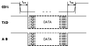
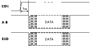
Figure 1. TDx 0 1D485H module data transmission timing diagram | Figure 2. TDx 0 1D485H module data reception timing diagram |
Size /suggested printing layout

Circuit design

| 
|
Figure 3. MCU 5V power supply application circuit | Figure 4. MCU 3.3V power supply application circuit |
Figure 3 shows the connection diagram of the UART interface of the 5V MCU system and the TD501D485H isolated transceiver module. The module must be powered by a 5V power supply. The matching level of the TXD, RXD and CON pin interfaces of the module is 5V and does not support the 3.3V system level. Figure 4 shows the connection diagram of the 3.3V MCU system UART interface and the TD301D485H isolated transceiver module. The module must be powered by a 3.3V power supply. The matching level of the TXD, RXD and CON pin interfaces of the module is 3.3V, and it does not support the 5V system level.
|
|
Typical recommended circuits for EMC
Since the A/B line inside the module comes with a pull-down resistor and ESD protection device, it is generally not necessary to add ESD protection devices when used in good environments, such as the typical connection circuit diagram shown in the typical application in 8.1. However, if the application environment is relatively harsh (such as high-voltage power, lightning strikes, etc.), it is recommended that users must add TVS tubes, common mode inductors, lightning protection tubes, shielded twisted pair wires or single point ground connections to the same network at the A/B line end.

|
Figure 5. EMC recommended circuit |
If you need to meet specific surge level requirements, it is recommended to use the recommended protection circuit shown in Figure 5. Table 1 gives a set of recommended device parameters. The recommended circuit diagram and parameter values are only used as reference. Please determine the appropriate parameter values according to the actual situation.
Table 1. EMC recommended parameters Label model Label model C110μF, 25VTVS1SMBJ5.0AC2102, 2KV, 1206TVS2SMBJ12CAGDT3RL090M-5-STVS3, TVS4SMBJ6.5CAR11MΩ, 1206T1B8279S0513N201R2120Ω, 1206U1TDx11D485H module
|
Precautions for product use
1 MCU IO port level matching
The matching level of the TXD, RXD and CON pin interfaces of the TD501D485H is 5V and does not support the 3.3V system level; the matching level of the TXD, RXD and CON pin interfaces of the TD301D485H is 3.3V and does not support the 5V system level.
2 Module RS485.AB bus level threshold description
From the truth table characteristics, it can be seen that when the A/B line differential voltage is greater than or equal to -10mV, the module reception level is high; when the A/B line differential voltage is less than or equal to -200mV, the module reception level is low; when the A/B line differential voltage is greater than -200mV and less than -10mV, the module reception level is in an uncertain state, and it is necessary to ensure that the module reception is not in this state during design. Therefore, when users design or apply RS-485 network, they should decide whether to add a 120Ω terminal resistor based on actual conditions. Principle of use: No matter whether the RS-485 network is in a static or dynamic situation, it is necessary to ensure that the A/B line differential voltage is not between -200mV and -10mV, otherwise communication errors will occur.
3 Module RS485 sending and receiving data control pin CON level description
From the truth table characteristics, it can be seen that this series of embedded isolated RS-485 transceiver modules send data when the CON pin is low and receive data when the CON pin is high, which is opposite to the transceiver control level of ordinary RS-485 transceiver chips. Therefore, if the customer wants to change the same transceiver control level as the ordinary RS-485 transceiver chip, it is recommended that the user add a reverse circuit between the MCU and the module CON pin.
4 module pin description
Module 6. When pins 7 and 10 are not used, please dangle this pin;
When using the user, be sure to avoid short circuit between the VO pin and the RGNDRGND pin, otherwise the module will be damaged. In addition, the VO pin is only used for pull-up resistor circuits and should not be used for other circuits.
5. Use of shielded cables
For data transmission lines, please choose shielded twisted pair wires, and the shielding layer of the same network should be connected to the ground alone; if the RS-485 network is required to have better anti-interference capabilities, double-layer shielded twisted pair wires can be used, and the RGND of each node is connected to the inner shielding layer, and the outer shielding layer is then connected to the ground alone.